Ribbon: Output -> CAD to G-code
The program allows creating a control program (CP) in the G-code file format for CNC machines. G-code files are generated directly from DWG/DXF drawings. The following entities can be converted to G-code: lines, polylines, circles, arcs, ellipses, splines, texts, multiline texts and hatch.
To convert a file to G-code use the following instruction:
1.Open a DWG/DXF file and edit it if required.
2.On the Output tab in the Conversion group select the CAD to G-code command.
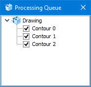
3.By default all drawing contours are converted. If you do not need to convert any particular contours, open the Processing queue window and uncheck them.
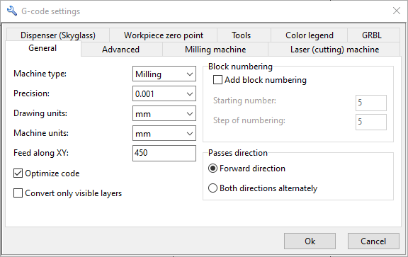
4.By default ABViewer generates a control program for a milling machine. To generate G-code for a laser machine select the required machine type in the G-code settings window on the General tab.
5.Click the Convert button. G-code will be generated automatically.
6.Click the Save G-code button. In the opened window enter the output file name and click Save. The file will be saved with the NC extension.
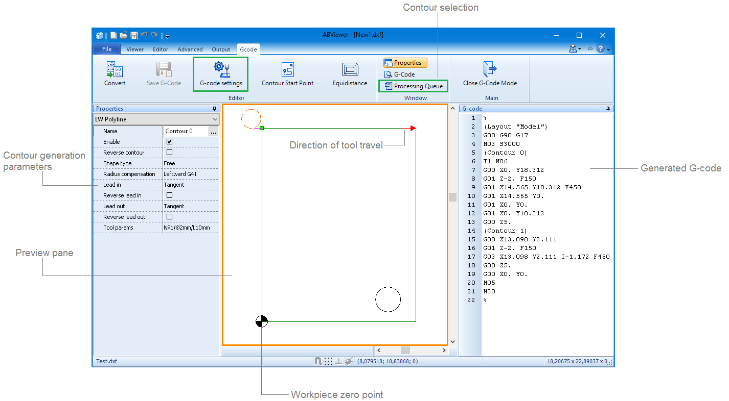
There is a toolbar under the G-code window name:
Contour selection
You can indicate the sequence in which the contours will be processed in the Processing queue window. To change the contour position use the context menu or move the contour to the required position with the mouse. Only contours selected with a check mark in the contour list will be converted.
Preview pane
The opened drawing, the workpiece zero point, the start point of the tool movement, tool direction, the tool lead in/lead out method and the tool are displayed in the preview pane. The display of elements in the preview pane can be adjusted on the Color legend tab of the G-code settings window.
The user can select the required contour by clicking on it in the preview pane. The context menu is called with the right mouse button.
Properties
The tab includes additional tool settings: tool direction, lead in/lead out method, tool radius compensation. These settings are displayed in the preview pane.
Enable |
Includes a contour in the G-code precessing list. |
Reverse contour |
Changes tool direction from the start point along the selected contour. |
Shape type |
Defines a contour type. |
Radius compensation |
Tool radius compensation. The Off (G40) option discards tool radius compensation. The Leftward (G41) option compensates tool radius on the left of the trajectory. The Rightward (G42) option compensates tool radius on the right of the trajectory. For GRBL, the tool trajectory. It is created using the tool radius with the help of the equidistance. With the Inside option, the movement trajectory is located inside of the contour. With the Outside option, the movement trajectory is located outside of the contour. |
Lead in |
Sets the tool lead in method. The user can select one of the following lead in methods: tangent, normal, arc. Changes of the lead in method are displayed in the preview pane. To change the tool lead in direction tick the Reverse lead in checkbox. |
Reverse lead in |
|
Lead out |
Sets the tool lead out method. The user can select one of the following lead out methods: tangent, normal, arc. Changes of the tool lead out method are displayed in the preview pane. To change the tool lead out direction tick the Reverse lead out checkbox. |
Reverse lead out |
|
Tool params |
The drop-down list includes the tool and its parameters. The list is completed with the data from the Tools tab of the G-code settings window. |
G-code settings
The G-code settings window includes the following tabs with settings: General, Milling machine, Laser (cutting) machine, Workpiece zero point, Tools, Color legend, Advanced, Dispencer (Skyglass), GRBL, Lathe machine.
Color legend
Additional elements that will be displayed in the preview pane are selected by checking the corresponding element in the Color legend tab. To change the element color the user needs to click the corresponding color square. After it the standard Color window in which the user can select the required color will be opened.
Settings |
Description |
Code Example |
|
General |
|
Forward direction |
The tool moves in the direction pointed by the arrow in the preview pane. |
- |
Both directions alternately |
At first the tool moves in the pointed direction and then backwards. |
- |
Machine type |
Sets the machine type: Milling/Cutting. |
- |
Precision |
Sets the number of digits after the decimal point. |
- |
Drawing units |
Sets drawing units. |
- |
Machine units |
Sets machine units are set. If units do not coincide, they are converted. |
- |
along XY |
Speed of XY-direction cutting feed. If it is equal to 0, this value is ignored. |
F450 |
Add block numbering |
Adds numbering of blocks in the control program code. |
N5
|
Starting number |
Initial number of block numbering (default value: 5). |
|
Step of numbering |
Step of numbering. |
|
Add program name |
Adds program name to the control program code. |
O001 |
Show comments |
Shows commentaries in the control program code. |
(Layout "Model"), (Contour 0), (Contour 1) |
Show percent sign (%) |
Adds the sign % to the control program code. |
% |
Optimize code |
Enables the code optimization - repetitive commands and coordinates are not duplicated. |
- |
|
Milling machine |
|
Feed along Z |
Speed of Z-direction cutting feed. |
F150 |
Spindle speed |
Rotation frequency of the spindle. |
S3000 |
Feed depth along Z |
Depth of penetration into a workpiece. |
G1 Z-2 |
Retract height |
Shifting of the tool from the workpiece in Z-direction. |
G0 Z5 |
Pass depth |
Depth of penetration per one pass. The number of passes is calculated automatically. |
|
Full-depth path |
Feed depth for the full penetration depth. |
|
Number of passes |
The number of passes calculated on the basis of the feed-pass ratio. |
|
|
Laser (cutting) machine |
|
ON command |
Command used to turn on the laser. Default value: M3. |
M3 |
OFF command |
Command used to turn off the laser. Default value: M5. |
М5 |
Dwell (G4) |
Delay of the program run. |
G04 P100 |
Add power commands (M10, M11) |
Turns on/off power commands. |
M10 Q128/M11 |
Number of passes |
The number of tool passes along the contour. |
- |
Laser turning off before G0 |
Turns off the laser before a rapid move. |
|
|
Workpiece zero point |
|
Drawing zero point |
Setting the workpiece zero point. |
- |
Top left point |
- |
|
Top right point |
- |
|
Bottom left point |
- |
|
Bottom right point |
- |
|
Additional offset |
Additional offset in X- and Y-directions. |
- |
|
Tools |
|
No. |
Number of the tool. |
T1 M6 |
Diameter, mm |
Diameter of the tool. |
|
Length, mm |
Length of the tool. |
|
|
Advanced |
|
Add program name |
Adds the program name to the title. |
О |
Show percent sign (%) |
Adds the special sign (%) in the beginning and in the end of the file. |
- |
Trailing zeros |
Fills the coordinate with zeros taking into account the number of digits. |
- |
Show contour name |
Adds a contour name. |
(Contour 0) |
Show layer name |
Adds a layer name. |
- |
Convert an arc to lines |
Uses the G1 commands instead of G2/G3. |
- |
Start at the position X0 Y0 |
Start from the position 0. 0. |
- |
|
|
|
CNC type |
Selection of the CNC machine type. |
- |
|
|
|
ON command |
Turns on the dispensing CNC machine. Default value: M7. |
М7 |
OFF command |
Turns off the dispensing CNC machine. Default value: M9. |
М9 |
Turn off the pump at |
Turns off the pump at the specified number of mm away from the contour end. |
- |
Straighten contour |
Uses the most straight trajectory while creating a contour. |
- |
Merge points |
Merges contour points in the specified radius. |
- |
Pump ON |
Turns on the pump. |
М10 |
Pump OFF |
Turns off the pump. |
М11 |
|
Lathe machine |
|
X-axis of the drawing into the machine Z-axis |
Transformation of a drawing axis into a machine axis. |
- |
Y-axis of the drawing into the machine X-axis |
Transformation of a drawing axis into a machine axis. |
- |
Feed along XZ |
Speed of XZ-direction cutting feed. If it is equal to 0, this value is ignored. |
F |
Go to ABViewer