Quick Access Panel:
Ribbon: Output -> Print… -> Print preview
Menu: File -> Print… -> Print preview
Hotkey: Ctrl+P
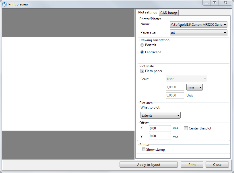
The Print preview dialog box consists of the preview area and the print settings area. It has two tabs: Plot settings and CAD Image.
The Plot settings tab allows selecting the needed parameters for plotting the current drawing.
Printer/Plotter
The section is used to select the plot device and the output paper size.
Drawing orientation
The section enables the choice of the paper orientation:
Portrait - orients and plots the drawing so that the short edge of the paper represents the top of the page.
Landscape - orients and plots the drawing so that the long edge of the paper represents the top of the page.
Plot Scale
The section allows selecting the needed scale and setting a custom scale factor. The scale option defines the exact line length on the paper sheet and the one in drawing units ration. This correlation is expressed by the following formula: X = Y, where X – is one millimeter (or inch) of a sheet, Y – drawing units. Thus, Scale factor: 1:2 means that 1 sheet millimeter will contain two drawing points.
The Fit to paper option plots the layout into one sheet.
Plot area
The section is used to select the area to be plotted. The following options are available:
Extents plots the part of the drawing that contains entities.
Layout plots the whole layout with the origin 0,0 in the drawing
Window plots the selected by the window area
Display plots the current displayed area
Offset
The setting allows specifying the offset coordinates.
If the option "Center the plot" is checked, the image will be located in the center of the paper.
Restore Settings
The button [Default] sets all the parameters as default ones.
The CAD Image tab sets the CAD files display when plotting. It is possible to specify the line weight, color mode, texts and dimensions display in the drawing when plotting. These settings do not influence the drawing file, but its output settings.
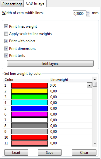
Width of zero-width lines
Specifies the width of the lines, which have a width equal to zero, in chosen units (inches or millimeters) for printing. All entities with null-width will be printed with the width equal to the entered value.
Print lines weight
If the option is checked all the entities with null (zero) width will be printed with the width equal to the one entered in the edit box Width of null-width lines, and all the entities with zero-width will be printed with the width of 1 pixel.
Apply scale to lines weight
Use this property to scale lines weight according to the drawing's Scale factor.
Print with colors
Displays the drawing (image) in the color or black-and-white mode.
Note: use black-and-white mode for printing if you use black-and-white printer and want to have all the lines with the same weight and intensity.
Print dimensions
Allows printing dimension entities if they exist.
Print texts
Allows printing text entities if they exist.
Edit layers – calls the Layers dialog.
Set line weight by color
In CAD color system each color is identified by an AutoCAD Color Index (ACI) number, an integer from 1 to 255. Standard color names are available only for colors 1 to 7. These colors are names in the following way: 1 Red, 2 Yellow, 3 Green, 4 Cyan, 5 Blue, 6 Magenta, 7 White/Black.
This option allows manual definition of the line weight according to its color.
Press Save... button to save already made settings.
Press Load... button to load previously saved settings (file with CWS extension).
The Apply to Layout button applies the settings to the current layout
The Print button plots the layout.
The Close button closes the dialog box.
Printer
If the Show stamp option is active, the file name, layout name, current date and time are printed in the upper part of the drawing.
Go to ABViewer